Ferro Alloys - Furnace Control
 System Information System Information
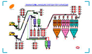
There are two independent systems each dedicated for one Furnace. Each system has two weigh hoppers, supported by four load cells and backed by four infeeders and one outfeeder (feeder - electro magnetic vibrating type). Different raw materials are received by the weigh hoppers through the infeeders which completes the weighing and batching cycle as per the preset recipe menu. After the completion of weighing and batching cycle by both the weigh hoppers, charge mix is unloaded to a running horizontal flat belt conveyor through outfeeders, charge mix received by the horizontal conveyor is unloaded into a skip and after full collection of the charge mix the skip starts upward movement. The skip halts at a fixed up position and unload the charge mix to a surge hopper and starts downward and halts at the fixed rest position at the bottom to collect another charge mix. The unloaded charge mix in the surge hopper is collected by a Telfer Car just below the surge hopper. The Telfer Car starts moving towards the Furnace hoppers and halts at a preset Furnace hopper to unload the charge mix into the Furnace hopper. After unloading, the Telfer Car comes back at the rest position just below the surge hopper and gets ready to receive another charge mix.
| Ferro Alloys - Furnace Control |
 |
 |
Bill of Materials
| • |
Two (2) systems (individual but identical) housed in a standard control desk format for automatic weighing, batching and transportation of Furnace feed raw materials complete with most friendly hardware and software as per the common industrial practice. Each system include batch controller, process computer, MMI with graphic monitor and other accessories like weight display units, selector switches, push buttons and mimics etc. |
| • |
16 nos Loadcells with mounting accessories (4 load cells for one weigh hopper), each loadcell 1.5T capacity, sensitivity : 1 mv/V. |
| • |
Co-axial cable 4C or 6C as per connection configuration of load cells. Four (4) lengths: each length approx. 100 mtrs. |
| • |
Four (4) nos Loadcells Junction Box |
| • |
Four (4) nos Signal Transmitter (optional) |
Design Criteria
Each system shall have four modes of operation:
Automatic Mode
In this mode, recipe set points are entered into the recipe menu table in the computer, selection of the Furnace hopper is also entered. The Weighing and Batching system starts functioning based on the start command subject to the following confirmations:
| • |
Tare weight of weigh hopper is within the tolerable set limit |
| • |
In and Out feeders are in stop position |
Recipes collected into the weigh hoppers are duly weighed and batched and wait for transport system operation.
The transport system starts automatically after a pre-set delay subject to the following confirmation:
| • |
Horizontal conveyor running |
| • |
Skip at the down position |
| • |
Telfer Car is at rest position (i.e. just below the surge hopper) |
After getting confirmation on the above points, the outfeeder starts and stops after emptying the weigh hoppers. The out feeder stops at a stable way after confirmation of the Tare weight of the weigh hoppers within tolerable limit. Otherwise it stops at a preset delay when the Tare weight of weigh hopper is beyond safe limit without any further change in weight. Infeeders Operation is controlled through coarse / fine feed mode.
During this process, the following alarms will be generated in audio-visual mode. The alarms description shall be displayed automatically through alarm menu in the computer followed by spontaneous printout. The alarm arises after a preset delay from real time of occurrence.
Alarms
| • |
Infeeder slow feed rate |
• |
Outfeeder slow feed rate |
| • |
Tare weight out of limit |
• |
Infeeder does not start |
| • |
Infeeder does not stop |
• |
Outfeeder does not start |
| • |
Outfeeder does not stop |
• |
Hopper I weight overshoot |
| • |
Hopper II weight overshoot |
• |
Horizontal conveyor stops / not running |
| • |
Skip not in down position |
• |
Telfer car not in position |
| • |
Telfer car not taken correct hopper position |
• |
Skip not reached up position |
Whenever an alarm is raised, the system automatically goes to manual mode. From manual mode, the system is accessed to automatic mode.
The following reports shall be generated during this process:
| • |
Shiftwise (A/B/C) Recipe Management Table |
• |
Daywise Recipe Management Table |
| • |
Shiftwise Recipe Distribution for Furnace Hoppers |
• |
Daywise Recipe Distribution for Furnace Hoppers |
| • |
Shiftwise overshoot compensation for Furnace Hoppers |
• |
Daywise overshoot compensation for Furnace Hoppers |
| • |
Shiftwise Recipe Batch Counts |
• |
Daywise Recipe Batch Counts |
| • |
Shiftwise number of stops of the auto mode |
• |
Daywise number of stops of the auto mode |
Similar monthly report of each kind shall be generated.
The process computer shall log all the processing data for report generation and carry forward for further process.
Semi-Automatic Mode
In this mode, the system shall be operated without process computer. Other peripherals shall help the system functioning. Batching is carried out by the batch controller through inbuilt set point management procedure. Transportation is carried out through PLC. Selection for furnace feed hopper is done through path selector switch.
Semi-Auto Manual Mode
In this mode, the system shall be operated without process computer and PLC. Other peripherals shall help the system functioning. Batching is carried out by the batch controller through the inbuilt set point management procedure.
Transportation is carried out through manual push buttons.
Manual Mode
In this mode, entire operation is carried out through manual push buttons only.
In case of alarm, the manual mode overrides all other modes. Back to any mode shall be through manual mode only. |